Need help with a project - Source Optimization "test"

If anyone would be interested in coming up with multiple choice questions for this thing, go ahead and just post them. Try to make them require actual thought, and not just memorization or fact regurgitating.
I am not looking for jokes or people trying to be smart asses. Serious input only, please.

My meaning is only complement with practical situations what you were suggesting  I'm just saying because you knowm, even though we all know more or less the theory, sometimes you want a specific layout (because of aesthetic or puzzle purposses) that it's actually difficult to optimize perfectly like open areas with surrounding side-rooms where enclosing the leafs is not so easy and such...
What do you think about it? 
A) The wall of your test chamber.
B) The clipped frame around the testchamber door.
C) Sculpted terrain brushes/displacements.
D) Static props, such as diversity vents.

What is the best way build it.
a) Just build it already and pop the player in and just forget about the windows.
b) Just build the building. And put a skybox in front of all the windows.
c) Build the building and build the exterior with func_details as far as the eye can see.
d) Build the buildings and build the exterior as far as the eye can see.
To let the employees of aperture chill a bit Aperture decides to build a garden.

What's the best way to fake the grass?
A) Just make a grass brush.
B) Make a grass brush; grab the carve tool and make it look pretty.
C) Make a grass brush; grab the carve tool and make it look pretty; then make it a func_detail.
D) Make a grass brush; make it a displacement.
E) Make a grass brush; make it a displacement and put a nodraw brush underneath it.
Because the people at Aperture decide it's time to make a nice building inside a big square room.
However; after building the garden and the exterior they're running a bit low on render budget.

What's the best way to build the pillars?
a) Build the brush based pillar.
b) Build the brush based pillar and make it a func_detail
c) Build the brush based pillar and make it a func_brush
d) Create a custom prop_static model.
e) Create a custom prop_physics model.
f) Create a custom prop_dynamic model.
Aperture found images of an abandoned factory and want to build it they hire you to build it for them.
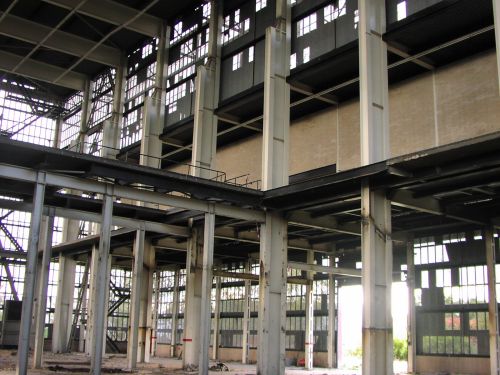
What would you make func_details?
A) Nothing.
B) The pillars.
C) The second floor
D) The second floor and the pillars
E) Everything but the ceiling and the brick wall
F) Everything but the ceiling
G) Everything!
What is the best way to divide this hallway into visleaves?
visleaves.pngHMW wrote:
What is the best way to divide this hallway into visleaves?
visleaves.png
None of the above. Sorry HMW
josepezdj wrote:
posting some basic test maps to optimize, like practical exercises
This is the best thing you said in your whole paragraph of text. Giving out example maps with solutions is a great way to get people to optimise.
I might like to make one of these maps.
HMW wrote:
What is the best way to divide this hallway into visleaves?
visleaves.png
Option E:
------------------
|      /  \      |
|     /    \     |
|    /------\    |
|   / |    | \   |
|  /  |    |  \  |
| /   |    |   \ |
HMW wrote:
visleaves.png
...whoopsy daisy 
In regards to josepezdj's post, the example maps sound like a great idea. I might toss one together.
Should we make some that have optimization errors as well? (incorrect usage of func_deatiling, incorrect usage of hint/skip brushes, stuff like that)
taco wrote:
Option E:```
| / \ |
| / \ |
| /------\ |
| / | | \ |
| / | | \ |
| / | | \ |
```
Unless you have a crazy amount of detailed stuff right around the corner, that is complete overkill.
HMW wrote:
Unless you have a crazy amount of detailed stuff right around the corner, that is complete overkill.
That's how I have always done it bro. And it is the best way.
FelixGriffin wrote:
As a not-very-good optimizer, I don't really understand what makes those options better or worse. I know what visleaves are, but how do you figure out which arrangements are best?

You are where the star is. The visleaf where you are is colored green.
Now draw lines to see what can see what (purple lines).
All visleaves you can see are now colored orange.
The image with the least green/orange is the one that renders the least, therefor that one is the best option.
In this case the best answer is:
E, C&B, A, D (although hammer will make a visleafs there anyways, C or A, depending on its mood.)
Hopefully that helps
But that diagram is foolproof.
If anyone can come up with more visual examples for hints, please do. I'm a fan of the "two adjacent rooms connected by a corridor" one. I don't want anyone to start thinking too narrowly about what needs to be done by using the same specific example over and over.
And I really like the idea of a VMF that needs to be "fixed", but for the purposes of this test (which will be a multiple choice "quiz"), let's stick to visual examples and other types of multiple choice questions.

or maybe something else?
Hint 1

Hint 2: What seems to work? What doesn't?
Hint 3: Can you try something else maybe?
Answer
||The diagonal cuts like in the second image are working: If we stand on one side the other side is hidden. The extra diagonal cuts in the final image are also a bit helpful, so if you have something that's expensive to render in that cornerx: put them in.
Generally however that part of the corner isn't the most expensive thing to render so I choose not to draw them in my solution, I don't think in this case they're worth the extra visleafs.
If you do have something expensive to render there though; do use the extra hint/skips!
The biggest problem we have is the problm that there is a very stretched corner between the bottom part and the separate top parts. You can draw lines almost parallel to wall that will stretch forever, making it almost impossible to do that with hint/skip!
So here's my solution:

As you can see; I kept the lines as in 2. And I added an AREAPORTAL where the green line is.
A hint wouldn't be effective here; we can draw a line through it from the top part. What you will be able to see is marginal; but the visleaf would still be rendered. 
With an areaportal you only have to render that small bit!  ||
||
taco wrote:
Option E:```
| / \ |
| / \ |
| /------\ |
| / | | \ |
| / | | \ |
| / | | \ |
```

However, as HMW pointed out, this will depend on the amount of entities to render into each leaf.
However, my suggestion about making a map with a "special layout" was right because there are some cases much more complex than just the example above, including several levels (the thrid dimension), not a single one as I guess there is in that example.
Lp, just a small typo in your first hint--in the fourth row, second column, the top left area looks like it should be orange. (I may be wrong on this.)
FelixGriffin wrote:
Lp, just a small typo in your first hint--in the fourth row, second column, the top left area looks like it should be orange. (I may be wrong on this.)
well yes of course My fault, sorry. If you're in a visleaf obviously the adjacent is visible! Cheers, should be fixed now!
josepezdj wrote:
interlopers image
However, as HMW pointed out, this will depend on the amount of entities to render into each leaf.However, my suggestion about making a map with a "special layout" was right because there are some cases much more complex than just the example above, including several levels (the third dimension), not a single one as I guess there is in that example.
A few things here:
- The interlopers tutorial has a 45 degree angle; this has a 60 degrees angle. The most important thing is that both ends can't see each other. That's done by drawing the line through the corridor.
- It's worth noticing that in this case both rooms aren't rendered at the same time with solution E:
https://dl.dropbox.com/u/37801279/twp/o ... skillz.png
- As for the third dimension: you can tread that the same as the 2d-version; but rather than using the xy plane you have to look at xz and yz planes; but the same rules apply.

Lpfreaky90 wrote:
- As for the third dimension: you can tread that the same as the 2d-version; but rather than using the xy plane you have to look at xz and yz planes; but the same rules apply.
Yeah I know but I'm meaning all at the same time: an upper room added to your case... it's easier to create a map and post it, or maybe only post some pictures of it
EDIT (further thoughts after chating with Lp)
-
I really think I won't use that specific layout because that layout is the problem itself for a good optimisation. I'd make those corners on the left middle of the drawing more closer so both meet my red line.
-
A good lesson a mapper should also learn is that while you're mapping you must have this kind of possible issues in mind and try to find the best layout possible that allows you the best (later) optimisation.
-
As an addition to the above point, even though we discuss "theorical situations" here, the mapper will have the last word about where could the player actually be in each case depending on the puzzle and elements; this way, the mapper can indeed think of a way to prevent rendering of many "costy" leaves by changing the puzzle to his advantage.
-
Even though I created more visleaves with my division, this DOESN'T mean a worse optimisation, maybe slightly a more compiling time, but not a worse performance. However I'd change a bit those angles to make possible a better optimisation.
-
This problem we're discussing is about which areas can see the other ones, thus visibility, we should not forget bout that. Those lines I drew are actually dividing real visibility areas from the others. I'm not sure if in the end I would use them though (if I would ever have to use that layout
), if there were not many entities there in those 2 upper corners I isolated with my red lines, because they won't help much to a better performance.
So this would be my layout:
